Télescope de 193cm

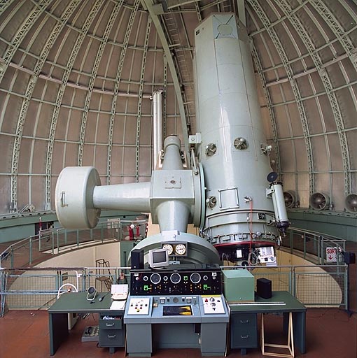
Le télescope de 193cm a été à l’origine doté de trois foyers différents : Newton (f/5), Cassegrain (f/15) et Coudé (f/32). Seul le foyer Cassegrain est utilisé maintenant.

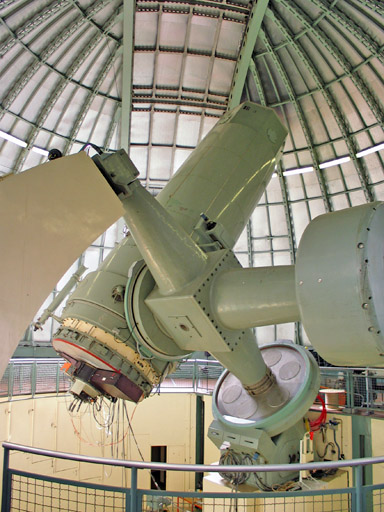
Sur la photo de gauche on voit la bonnette du spectrographe échelle SOPHIE montée au foyer Cassegrain, installé depuis août 2006. Le spectrographe lui-même est implanté au niveau de l’ancien foyer coudé, sous le pilier Sud.

Une nouvelle caméra CCD est prévue pour SOPHIE en 2022.

Un nouvel instrument a été mis en service en 2021 au foyer Cassegrain, en parallêle avec SOPHIE :
le spectro-imageur MISTRAL.

La bonnette d’interface Cassegrain (en noir sur la photo de gauche) permet l’installation occasionnelle d’instruments d’équipe comme l’instrument GHASP (réducteur focal + interferomètre Fabry-Pérot).

Une opération de jouvence du télescope est actuellement en cours. Une nouvelle caméra de guidage plus performante a été mise en service, pilotée par un nouveau logiciel. Un nouveau système d’encodeurs a été installé sur les axes alpha et delta. Ont été remplacés les moteurs alpha (rapide et lent) et delta (rapide et lent), le moteur du miroir sécondaire et le moteur de la marguerite par des moteurs à commande numérique. Les anciens moteurs de la coupole ont aussi été remplacés par des moteurs à commande numérique. Les moteurs du plancher mobile et ceux des ventilateurs de la coupole ont été changés. Les ressorts supportant la coupole ont été changés. Une webcam a été installé dans la coupole pour visualiser le télescope depuis la salle de controle. Une refonte du logiciel du télescope (y compris le modèle de pointage) progresse, visant à terme une semi-automatisation du télescope et l’asservissement de la coupole.

Le spectrographe à longue fente CARELEC, en service depuis 1986, a été décommissioné en janvier 2012.

Histoire du télescope de 193cm

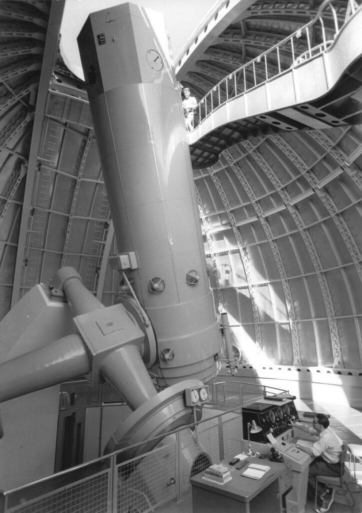
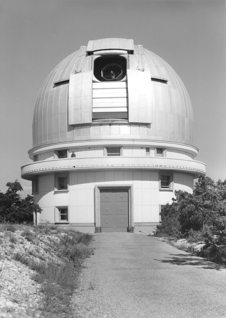
Ce télescope, construit par Grubb & Parsons à Newcastle (UK), fut monté pendant l’été 1957 et réceptionné en décembre 1957 avec un miroir factice en béton. L’optique fut installée début 1958. Les premières observations datent du 17 juillet 1958. Sur la photo de droite, J. Texereau est au pupitre de commande et R. Leblondet sur la passerelle Newton.

De nombreux instruments ont été utilisés dans le passé sur ce télescope (bonnettes photo, réducteurs focaux, plusieurs caméras électroniques différentes, les spectros Chalonge, “D”, NEOM, “O”, TGR, Nébulaire (Pellet-Deharveng), Roucas, BS, ISIS, et bien sûr le celèbre ELODIE). Le plus grand, le spectrographe Coudé, construit par la société REOSC, fonctionna entre Juillet 1959 et Février 1985.

SOPHIE échelle spectrograph

Summary

SOPHIE is a cross-dispersed échelle spectrograph permanently located in a temperature-controlled chamber in the second floor of the 1.93-m telescope building. First light with this instrument was achieved on July 31, 2006, but the first wavelength solution was obtained only on 24 August 2006. The spectrograph is fed from the Cassegrain focus through either one of two separate optical fiber sets, yielding two different spectral resolutions (HE and HR modes). The spectra presently cover the wavelength range 3872-6943 Å. The instrument is entirely computer-controlled and a standard data reduction pipeline automatically processes the data upon CCD readout. For late-type stars (F,G,K,M) this includes radial velocities by numerical cross-correlation techniques which can yield very accurate velocities (down to 2-3 m/s using simultaneous Th calibration), depending on the signal-to-noise ratio.

Apertures & modes

Each fiber set consists of two circular entrance apertures (3 arc-sec wide) separated by 1.86 arc-min in the focal plane (nominally in the E-W direction). They feed light into the spectrograph through optical fibers of 100-micron diameter. Fiber A is normally used for the target while fiber B can be used to obtain the sky spectrum or for a simultaneous calibration lamp exposure. Fiber B can also be masked. Both fibers A and B can be simultaneously illuminated by one of the calibration lamps, or by the sky.

The HR fiber pair includes optical scramblers designed to render the measured radial velocities largely insensitive to the exact position of the star in the entrance aperture.These fibers also incorporate a 40 micron tilted exit slit to achieve high spectral resolution (HR mode, R=75000). The other fiber pair is used when a higher throughput is desired (HE mode, R=40000), particularly in the case of faint objects. These average resolving powers near 5500 Å have been derived from the FWHM of extracted Th-Ar spectra in both modes. The difference in resolution can be seen in a comparison between the two modes in the red (6870 Å) region of the telluric water vapor bands. The difference in throughput between the HE and the HR modes is a factor of 2.5 (1 magnitude). Switching between the two modes involves moving the fiber heads in the adapter which takes about 3 minutes.

Acquisition and guiding

The adapter (or bonnette) carrying the optical fiber heads is mounted at the Cassegrain focus of the 1.93-m telescope. This is the same adapter used by Elodie which has been modified for Sophie. It includes a new autoguider CCD camera, the calibration lamps and atmospheric refraction correctors. The field of view of the autoguider is 4.6 arc-min. The telescope pointing system features digital encoders in both declination and hour angle with an accuracy of 5 arc-sec. A pointing model corrects for mechanical flexure and allows for accurate setting of the telescope. The coordinates are displayed in the observing room and in the dome. There are limits on the pointing of the telescope due to its asymmetrical english-type mounting.

Environment control

The spectrograph is enclosed in a thermally insulated chamber whose temperature is accurately regulated and humidity is under control. This chamber is located in an air-conditioned room where are located the instrument and telescope electronics. This room is separated from the observing area, which also air-conditioned, by a special insulated wall. This three-level temperature control ensures a high degree of thermal stability for the instrument. The spectrograph itself is mounted on shock absorbers and is supported by the telescope pier structure. Its dispersive elements are in a constant-volume vessel filled with Nitrogen so as to insure a constant pressure and thus a constant index of refraction. SOPHIE has now its own thermal insulation cover, so the final thermal configuration has been achieved. The temperature within the constant-volume vessel is now stable to ±0.01°.

Optical Layout

This illustration shows the principal optical elements of the SOPHIE instrument.

Dispersive elements

The 52.65 grooves/mm R2 échelle grating manufactured by Richardson (RGL), blazed at 65°, has dimensions of 20.4×40.8 cm and is mounted in a fixed configuration. The spectrum, as projected onto the e2V 44-82 CCD detector (4096×2048 pixels), yields 41 spectral orders, of which 39 are curently extracted, between 3872 and 6943 Å. See the list of orders for information on the details of the spectral format. Cross-dispersion is done with a OHARA PBL25Y glass prism of angle 31° and dimensions 28×22 cm. A color image of the echelle spectrum projected onto a translucent screen, obtained with a digital camera during the instrument integration process, shows the approximate spectral area sampled by the CCD chip.

Calibration lamps

Originally, the calibration lamps used were those mounted in the Cassegrain adapter designed for ELODIE : a tungsten lamp for relative flux calibration (“flat field”) and a Thorium lamp for wavelegth calibration. In order to improve the stability of SOPHIE, all calibration lamps (Thorium, Tungsten, LDLS and recently a Fabry-Perot étalon) are now housed in the same temperature-controlled room downstairs where ELODIE was located. Exposure times for all lamps are set automatically through the STS. Light from the Th lamp is filtered by a specially designed filter to cut-off light from strong near-infrared Argon lines which were polluting the Th spectrum.

Scattered light

The present level of scattered light in the interorder space is about 0.6 % of the signal in the orders for stellar spectra, as measured at the center of order 26 (corresponding to the center of the V band). This scattered component is due to infrared light from orders redward of 7000 Å which are not directly recorded by the CCD but which illuminate the optical elements and create a faint diffuse light which is superposed onto the observed spectrum. This was seen when the Thorium filter was first installed (see above).

CCD Detector

The CCD is a thinned, back-illuminated, anti-reflection coated e2V 44-82 chip with 4096×2048 pixels of 15 microns. The chip can be read out using two different settings:

ModeGainRONRead-out timeSaturation
Fast2.85 e-/ADU6.0 e- RMS18.8 s62000 ADU = 177000 e-
Slow0.68 e-/ADU2.1 e- RMS175 s65535 ADU = 44560 e- (25% well depth)

‘Slow’ read-out speed is recommened for S/N < 30. The bias level is measured over the full image when doing a calibration sequence, but accurate values are measured for every exposure using the 53-pixel overscan zones on each side of the CCD frame. WARNING: Make sure to do a bias exposure prior to any observing when changing CCD read-out speed (both for Fast to Slow and for Slow to Fast).

Calibration of the CCD gain and read-out noise can now be obtained using the new LED lamps installed in the spectrograph. Preliminary results confirm the above values for the Fast and Slow read-out speeds. The dewar maintains the CCD at -99° for a maximum duration of 48 h, but is automatically refilled every 24 h.

Signal-to-Noise

A plot shows the expected S/N ratio (per pixel) at 5500 Å as a function of the magnitude of a star (for standard exposure times of 5 minutes and 1 hour) in the two different modes: High-Efficiency (HE) and High-Resolution (HR). Observations obtained after the aluminization of the telescope optics in early September 2006 confirm these calculations.

Exposure meter

An exposure meter is presently available which gives the real-time plot of the exposure level. This system employs a H8259-01 Hamamatsu photomultiplier which measures part of the light ultimately lost due to obturation by the grating. A calibration of the count rate as a function of magnitude has been obtained in July and August 2007 for the HR and HE modes (plotted as black circles and red triangles, respectively). This calibration is valid for obj_A and obj_AB modes, but only valid for V<7 for thosimult mode.

Performance assesment

The gain in efficiency with SOPHIE in the V band has been determined to be 3 magnitudes in HE mode relative to ELODIE (and consequently 2 magnitudes in HR mode) by comparing S/N values (per unit wavelength) for the same star taken with the two spectrographs. Spectra of relatively faint sources are now well within reach, as shown during the science demonstration phase where a S/N (per pixel) of 27 (in V) was reached in 90 min for a V=14.5 object in HE mode. For a comparison between spectra of the same star taken with SOPHIE and ELODIE, see the case of a couple of interstellar lines present in the line of sight to Zeta Persei.
The stability of radial velocity measurements in HR mode is presently of the order of 3-4 m/s over several months. The short term stability is much better, as revealed by a recent observing run on Procyon where acousting mode oscillations of 50cm/s amplitude were detected. The relative velocity drift between fibers A and B has been measured to be 1.3 m/s, compatible with the error on the velocity zero-point.

Instrument software

Three (actually four) different systems are used when observing with SOPHIE.

Please read the new version of the Software User’s Guide (in french).

  • All spectrograph functions are controlled via dedicated software on a Windows workstation called ‘pcsophie’ which displays the complete status of the spectrograph and of the exposure in progress. All exposures are started from this computer. It talks to the CCD controller via a Linux workstation called ‘sophieccd’.
  • Observing sequences are prepared on a second Linux workstation called ‘sophiests’, or STS for short. All information needed for a given exposure (calibration or science frame) is normally entered through the STS. Parameters for the science exposures come from a user catalog which must be prepared in advance. These parameters are automatically transfered to ‘pcsophie’ where the exposure will be started manually once the telescope has been pointed to the target and the autoguider has been enabled. An estimate of the required exposure time can be requested from the STS, but is computed for an observation at the zenith.
  • The reduction of the data is done automatically on a third Linux worstation called ‘sophiedrs’, or DRS for short. For a science frame, this reduction includes bias subtraction, optimal order extraction, cosmic-ray removal, flat-fielding, wavelength calibration, cross-correlation with a suitable numerical mask and merging of the spectral orders. An off-line facility is available on the DRS for detailed examination of the reduced data and for additional cross-correlations.

Data reduction

The SOPHIE spectrograph features an entirely automatic data-reduction pipeline, adapted from the HARPS software designed by Geneva Observatory. This software performs localization of the orders on the frame, optimal order extraction, cosmic-ray rejection and wavelength calibration. Also computed for each order are the blaze function and a “one-dimensional” flat field, both derived from a Tungsten lamp exposure. The latter is derived for each order from the average of the rows perpendicular to the dispersion. The limited extent of the orders and the high quality of the CCD cosmetic response makes any further second-order flat-field correction unnecessary. The extracted spectrum is saved as an ‘e2ds’ FITS file, which contains the S/N values for each order and the wavelength solution polynomial coefficients. The orders are then reconnected after correction for the blaze function, yielding a ‘s1d’ FITS file with a 0.01 Å wavelength step, which includes the barycentric correction. All identification, calibration and reduction information is written into the file headers.

See the data products page for more detailed information. See also several examples of e2ds and s1d spectra for the hot star HD 34078 observed in HR mode.

Cross-correlation analysis

The data reduction pipeline on the DRS machine, which is controlled by the template specified through the STS, proceeds entirely automatically including the radial velocity cross-correlation and merging of the orders. Several numerical cross-correlation masks are available : F0, G2, K0, K5 and M4 and the closest one to the spectral type of the star is selected by the DRS. If none corresponds, by default the G2 mask is used. The on-line velocities are corrected to the barycenter of the solar system using the coordinates given in the STS catalog. On-line estimates of the line bisector, error on the velocity and v*sin(i) [if the B-V color is known] are also available. An off-line facility is available on the DRS machine for detailed examination of the results and further cross-correlations with any of the available masks. See the data products page for more detailed information.

User introduction

Each new observer is given a complete introduction by local staff to recommended observing procedures and tutored on software operation and data reduction as needed for succesful observing. This introduction normally takes place in the afternoon (14h local time) preceeding the first night of the run.

Beginning of the night

In order to prepare for an observing night, observers are advised to check in the afternoon (14-16h) that the user ‘sophie’ is logged on to the following machines :

  • ‘sophieccd’
  • ‘pcsophie’
  • ‘sophiests-2’
  • ‘sophiedrs’

If this is not so, log in with the (same) username/password available in the document you will find in the observing room. Follow carefully the detailed instructions given in this document which should lead you up to the start of an exposure and its full reduction. This will ensure you that the system is working correctly.

End of the night

The observer must report at the end of the night on any telescope or spectrograph technical problems using the web report form. A full report should be filled in at the end of the run and mailed to ohp.telescopes AT osuphytheas.fr. It is no longer necessary that you log off from the different machines at the end of the night.

Data archiving

At the end of your run, a special software tool, called DAU, is available to copy the raw and the reduced data onto a DVD or a USB pocket disk. All data taken with SOPHIE are automatically archived the next day onto an exernal system, ‘atlas’ (DELL PowerEdge R620, running Debian Linux, coupled to a PowerVault MD1200 raid array), hosting the SOPHIE Archive. Raw and reduced data are fully protected for one year, after which it is made available to the community. An extended 5-year protection can be granted for special projects by the relevant Time Assignment Committee. In this case, data still become available after one year but with time-related information masked. This information is unmasked after the 5-year period.

Night assistant

A night assistant is on duty at the 1.93-m telescope at all times (except for meal time around midnight) from sunset until start of nautical twilight and is responsible for telescope safety. He will open, close and turn the dome, point the telescope, start and set up the auto-guider. Observing is the responsibility of the astronomer. The night assistant is normally able to deal with most problems in the course of the night, but in very difficult cases he might call up resident staff for help. Phone numbers of on-duty personnel are listed in the observing room.

Should minor problems arise

Detailed instructions on how to overcome possible minor problems (“bugs”) with the software and hardware are available in the observing room. Check with the SOPHIE support astronomer or with the night assistant.

MISTRAL spectrograph camera

MISTRAL basics

MISTRAL is a low resolution spectro-imager adapted to the folded-Cassegrain focus of the 1.93m telescope via a focal reducer, in parallel with the SOPHIE adapter housing. A 45 deg mirror send the beam in one of the output sides to feed the MISTRAL instrument. This allows a very simple switch-over between the two instruments, without any mechanical operation.

The MISTRAL optical path is populated with an ANDOR deep depletion CCD 2K×2K camera (iKon-L DZ936N BEX2DD CCD-22031). The cooling is made by a 5-layer Peltier device. The operating temperature is -90℃ to -95℃. The dark current proved to be lower than 3 electrons/hour/pixel.

MISTRAL hosts two dispersors plus two empty slots on a mobile plate. They cover the full spectral range with a resolution of the order of 700. The instrument includes four Thorlabs motorized stages used to move/remove elements from the optical path: the slit, the grisms, the filters and the calibrating mirror. The FLI filter wheel has 12 positions for 50 mm filters (available : SDSS g’, r’, i’, z’ + Y, galactic H, OIIIa&b, Hα, SII).

Calibration lights (Hg Ar Xe spectral calibration lamps and Tungsten spectral flatfield lamp) are inserted within the optical path by four optical fibers via the calibration mirror which needs to be moved in. In order to facilitate the operability and stability of the instrument, all the calibration lamps, power supplies and electronic modules have been integrated directly in the mechanical structure of the instrument.

MISTRAL can offer two operating modes: regular observing runs in visitor mode and Target of Opportunity (ToO) in service observing mode for fast transients.

Science Basics

With the advent of new sky surveys, both from the ground and from space, the exploration of the variable sky is entering a new era. The high cadence of those surveys, and the large area covered allow a much larger coverage of the physical parameter space than ever before. As a result, a wealth of new phenomena and classes of objects are discovered, enlarging the physical diversity, and the statistics of previously known, but rare phenomena is greatly improved.

On the high-energy side, Gamma-Rays bursts (GRBs) are now observed in large numbers, and classified into two categories, the short- and long-duration GRBs. On the Supernovae (SNe) side, it appears that stellar explosions are not just core-collapse, or thermonuclear explosions of CO white dwarfs, but new categories are discovered, from ultrabright SNe to faint and fast decaying type I SNe, and passing through He detonations, Ia objects or luminous red novae. The range of underlying physical mechanisms must therefore be much more diverse than previously thought, but is still not understood. On a somewhat quieter side, Luminous Blue Variables, or numerous peculiar binaries await a better understanding too.

What is most necessary to progress is enough ground-based observing time to follow the variations of a series of representative examples of all those categories, both in photometry, and, even more so, in spectroscopy and in near infrared (Y band) spectroscopy: only with long time series of spectroscopic variations, accompanying the light-curves, it is possible understand the underlying physical mechanisms. Small to medium sized telescopes are best suited for that, being now more available than before (with 8m telescopes) provided they are equipped with efficient versatile spectro-imagers. This is the purpose of the MISTRAL instrument, mounted at the OHP 1.93m telescope. With a possibility of rapid changeover from the other available instrument (SOPHIE), it allows fast response to transient objects.

MISTRAL can also follow non transient targets in the framework of e.g. spatial missions covering fields as galactic HII regions and their exciting and triggered stars (e.g. Herschel) or nearby contributions to extragalactic surveys as for example XXL or XCLASS (XMM-Newton).

Observing Modes

MISTRAL allows several observing modes, accessible from a dedicated GUI, depending on the position of the different elements along the optical path. These elements are the filter wheel (12 positions), the spectral dispersors (blue and red VPH, associated with a blue and red intrance lens), and the slit (1.9 arc-sec wide). These elements are summarized in Table 1 and organised following the different operating modes. The Cook Book also gathers other useful informations about the CCD reading modes, the fringing occuring at the spectral red-end domain and the CCD optical distorsion in imaging mode.

Planning the Night

1) Working environment

The working environment for MISTRAL inside the T193 control room offers a personal visiting astronomer’s place, where you can install your personal laptop and connect it to an additional screen (through a VGA connection). To the right is a four-screen wall. Two are for the control of the spectrograph, and the two others are for preparation of the observations (exposure time calculators, night planner, etc.), data reduction (spectrum and images quick look tools…), web pages, etc. At the extreme right, you have a (cable-)phone (04 92 70 64 48).

The two upper screens are controlled by the MISTRALtube PC. This PC is physically mounted on the T193 telescope and it directly pilots the instrument itself. It offers a GUI to launch predefined MISTRAL observing sequences. There is the Maxim DL windows for image visualisation after acquisition, along with some pre-processing tools able to perform basic operations on the images (extraction of the flux along a line, a box, etc. + basic statistics on the regions).

The two lower screens are dedicated to observation preparation (exposure time calculators, night planner, etc.), data reduction (spectrum quick-look tool…), web pages, and all personal observer’s tasks. They also offer a coordinate server: This is the window showing the telescope coordinates, in principle located in the lower right screen. If not present, you have to launch the “TelescopeRADEC” icon (in the lower left screen).

The generated FITS files are first stored within PC MISTRALtube. They also are duplicated in the other PC MISTRALburo. They are located by default in the “DATA/date/username”. Username is the one requested in the Command Control MISTRAL window (upper right screen). Date is the current date. Data are also reachable through the “Access to data” icon on MISTRALburo.

2) Object observability

A planner is e.g. available from the IRIS telescope, it allows to compute the visibility of any object from the OHP site. It also allows to predict the distance to the moon and the moon illumination.

3) Estimated exposure times

— The Cook Book gives informations about the brightest observable objects still allowing a linear CCD/shutter response.

— A spectral exposure time calculator (ETC1) is available to give to the observer a typical exposure time for his/her targets in spectroscopic mode. It offers the choice of the chosen wavelength range (blue/red), of the expected seeing, of the target V band magnitude, of the required S/N for the expected most intense spectral line, of the nature of this line (absorption or emission), and of the physical shape of the target (point source or extended source modelled by a Gaussian). In order to give a quick flavour of the faintest reachable objects you can hope to measure with MISTRAL, Table 2 summarizes the V band magnitudes corresponding to a total exposure time of 1 hour, with a minimal S/N of 3, for point sources, and under a seeing of 2.5 arc-sec.

— Two other exposure time calculators (ETC2, ETC3) are available to give to the observer a typical exposure time for his/her targets in imaging mode. ETC2 gives you the exposure time needed to detect objects at a given magnitude with the requested S/N. ETC3 gives the exposure time needed to detect objects at a given magnitude with a probability larger than the requested one. As for the spectroscopic ETC1, Table 3 gives a quick flavour of the relation between exposure time and reachable magnitudes, for grizY bands and different seeing conditions.

Other useful information (e.g. the OHP sky light pollution) is available in the Cook Book.

4) Overheads and typical operating times

The maximal durations of different observing steps as recorded during MISTRAL qualification runs is given here. These maximal durations correspond to objects very difficult to locate as e.g. transients embedded in large galaxies. Most of the time, steps are therefore achieved faster than the listed durations. Some steps also depend on the astronomical object characteristics and Table 4 gives these durations as a function of several object V-band magnitudes.

5) Guiding

“This guiding offers a ~70arcmin² accessible field of view. This allows the telescope to automatically guide on V<17 stars. This guiding device being physically attached to MISTRAL, it is not strongly affected by mechanical flexions. It ensures a punctual object to stay within the slit for at least 2 hours. Basically all sky positions have at least a suitable star for guiding, and 85% have at least three (see Cook Book for more details).”

6) Focus

In addition to times in Table 4, observer has also to schedule in his observing plan at least one telescope focus per night. This is done in general at the beginning of the night and the required duration for this operation is generally less than 5 minutes. Other (much shorter) focusses may have to be done during the night if external conditions are strongly varying.

7) Field rotation

Despite the fact that the MISTRAL instrument or slit can not be rotated by itself, the T193 telescope adapter allows to rotate the field. This operation can be useful when several objects are visible in the field in order to fit more than one target within the MISTRAL slit. This task is not automatized for this telescope but can be manually done by the night assistant. The typical duration of such a task is of the order of 5 minutes if you already know the slit P.A. you want to apply. Note that for a purely north-south orientation of the slit, you have to set the rotator at between +3 and +4 °.

A Typical Night

0) Before the night

It is strongly recommended to estimate imaging and spectral exposure time prior to the beginning of the night. These can always be adapted during the night depending on the observing conditions.

— It is crucial to know the magnitude reachable in imaging mode versus the exposure time. This allows to predict exposure times needed to e.g. detect transients and to place them through the slit for spectral purposes. The basic way is to use the previous tables, but it is recommended to use the imaging ETCs (ETC2, ETC3) to have an exposure time more adapted to several parameters as airmass, seeing, sky transparency, ..etc… ETC2 predicts an exposure time for a given magnitude and detection percentage, disregarding the signal to noise. This case is adapted to be sure to detect a target to place it within the slit, without beeing intrinsically interested in the object image itself. ETC3 gives you an exposure time to detect an object at a given magnitude and at a given signal to noise. This is more adapted to studies requiring to use the images for themselves, for example if you want to make some basic morphological studies as star/galaxy separation.

— It is even more crucial to know for how long you need to expose your target in spectroscopic mode to reach your scientific goals. This exposure time can be estimated using ETC1. It offers the choice of the chosen wavelength range (blue/red), of the expected seeing, of the target V band magnitude, of the required S/N for the expected most intense spectral line, of the nature of this line (absorption or emission), and of the physical shape of the target (point source or extended source modelled by a Gaussian).

— Let’s assume these steps have been satisfied and that you are in the telescope control room, in front of your screen wall. In principle, you should find the whole system online when you arrive at telescope. If this is not the case, the process to follow is described in Section I 9) of the Cook Book.

1) first step : offsets

These are 0 sec CCD exposures with closed shutter before or after the night. This can even be done during day time. This is the less penalizing step because offsets are very stable with MISTRAL (see the Appendix) and could be approximated by subtracting a constant. We note that observing Darks is not mandatory (the Dark Current is less than 3 e-/hour/pixel). They do not increase significantly the reduction quality with MISTRAL.

2) second step : imaging flatfields

This is crucial in order to correct for the CCD response inhomogeneities across the field of view. This simply consists in observing a uniform light source and then deducing the CCD response. This uniform light source can traditionally be a white screen enlighted by some continuous lamp (domeflats), or the sky itself before the dark night, when stars are still below the sky level (skyflats). The T193 telescope has no flatfield screen on the dome, so the best way is to use the sky technique.

  • Do not forget to observe skyflats in all the filters you plan to use, as imaging flatfields can be VERY different from a filter to another one (see the Appendix).
  • Do not observe a single flatfield image per filter as you will have no way to get rid of statistical variations. Usually, observing five flats per filter is a good compromise between statistics and time needed to achieve the task.
  • Exposure times are very variable and depend on the sky level. However, we do not recommend to expose for more than 1 minunte because it may cause the first stars to be detected (or the flat to be saturated)

More details are available in the Cook Book.

3) Getting a usable spectrum

The process of getting usable spectra of a given astronomical object consists in the following steps. Automated procedures are designed to move the MISTRAL elements for each of these steps.

— (1) point telescope at the right place: this is done in imaging mode with the most favourable filter according to the object characteristic. Starting from theoretical coordinates, the telescope is approximately pointed and a first image is acquired (mode 3 of Observing Modes: “Preview image”, then “start exposure”) and compared to a finding chart. The usual pointing accuracy of the telescope (but depending on hour angle and declination) is presently small enough to have your target within the MISTRAL field of view. The process is iterated until a satisfactory telescope position is reached. The mode (3) save the images you got. Finally a guiding star has to be found. This is the task of the night assistant. Given the actual T193/MISTRAL capacities (sensitivity, FOV), he should be able to find such a suitable star in 99% of the sky regions.

— 2) Whatever the target, you then have to determine the slit position. For this, you have to use the “Search Slit Position” mode (mode 5 in the GUI) within the Command Control MISTRAL window and press “start exposure”. This moves the slit in the optical path. An image (rapid reading mode) is then automatically taken and shows the sky through the slit. A pop-up window propose an x-position of the slit (has to be close to 1040, unless smething went wrong). You have to validate it by clicking on “OK”. At this step, you should see the slit on the image (upper left screen). If slit is not visible or x-position is very different from the 1040 value, you have make the operation again (should not occur).

— (3) Place target at the slit position. Two situations are possible: target is a relatively bright object and you can see it in imaging mode with exposure times typically shorter than ~10 seconds, or, target is too faint to be detected with exposure times of ~10seconds.

— (4) You can now launch a “Science Spectrum” + “start exp” (mode 7 of the GUI)

— (5) get spectral calibrations (modes 8 and 9 of the GUI): these two last steps (wavelength calibrations and spectral flat fields) involve the injection in the instrument of the light from Hg Ar Xe spectral calibration lamps and then from Tungsten spectral flatfield lamp. They can be done after step (4).

— (6) Panic mode: not that it will (systematically) happen during a “typical night”, but you may experience troubles with the system. So we summarize different steps to exit this panic mode.

4) Data Archival

Raw MISTRAL data will be automatically archived (see Cook Book, section V4) within a database hosted by the CeSAM. Raw data are visible but not accessible during a proprietary period of 12 months to people other than PI. All calibration data are immediately public. A possibility is also offered to the observers to store/make available their final reduced data and added values through the ASPIC national service.

Night Spectral Data Quick Look

A local reduction tool is provided. It is able to give you a real-time basic spectral reduction (= a 1D spectrum) to judge if your data are good enough for your science goals, as well as a more complex data reduction with an optimised cosmic ray removal and a flux calibrated version of the final 1D spectrum. The basic version of the code is very fast to run and is operable in real time during the observations. The more complex version takes a few minutes to run. It is usable during the night if you have relatively long exposures, but was originally designed to be used during day time.

This code is based on the Automated SpectroPhotometric Image REDuction package (author: Marco Lam) and has been tuned to the MISTRAL needs. This is a Python code, available at the T193 observing room (and not requiring any Python knowledge). Iconized in the lower right screen of the mistralburo PC, it will first ask you the files you want to involve in the data reduction through a graphical interface, and the places in the raw 2D spectrum where you want to extract the object and the sky. Then, it will automatically produce a 1D wavelength calibrated spectrum.

More precisely, it starts from a raw 2D science spectrum (+ a calibration star for the flux calibration version), and uses spectral flat fields, wavelength calibration 2D spectra, and offsets that you provide. These files are listed in a ascii file created by the graphical interface (which you do not have to edit).

With this input list, the code will automatically:

  • provide an automatic detection of the objects in the science spectral image, extract and draw a non wavelength calibrated 1D spectrum
  • make an automatic wavelength calibration along the object path : calibration lamp automatic line detection and identification
  • provide a (non flux-calibrated) final 1D spectrum taking into account the observatory extinction curve and give a visualisation of this spectrum available in linear or log scale.
  • optimally correct for cosmic rays and provide a flux-calibrated 1D spectrum for the more complex version of the code.

The whole process is taking a few dozen seconds for the basic version and a few minutes for the flux-calibration version of the code. It only requests to launch the “quicklook.py” icon on the reduction PC, selecting the files you want to examine, and providing the code with approximate initial and final wavelength (Lambdamin, Lambdamax), the Y line where the object to extract resides (row), minimal level detection of lines in the wavelength calibration image (level), and widths of objects and sky extraction (a, b, and c). The style of command the icon is launching is: python3.6 quicklook.py Lambdamin Lambdamax level row a b c

We give in the Cook Book the contents of “quicklook.py”.

ToO Process

MISTRAL was also built in order to be able to follow target of opportunity (ToO) procedures.
When you submit a MISTRAL proposal, you therefore have the possibility to request ToO observations.

1) Alert mode general rules

Not all nights are opened to possible ToOs and a potential ToO observation is subject to the following rules :

  • A shared calendar gives the nights able to host a ToO observation (link will be given to granted PIs). This calendar is regularly updated to take into account technical events on the instruments/telescope. It is also taking into account the fact that, due to internal rules, an alert can not occur more frequently than one time every 3 nights.
  • There are two kinds of possible alerts : day-time trigger by contacting the OHP director, and night-time trigger for urgent alerts requiring an immediate (< 1 hour) reaction.
  • Night time trigger : the night operator is in charge of deciding to go (or not) on the target. Decision tree is as follows :
    • night status has to be “open” (see shared calendar)
    • there is a validated ToO proposal, with still available time
    • weather is OK
    • MISTRAL is working/mounted
    • target is observable (coordinates, telescope inclination, etc…)
  • The maximal duration of an alert in 2 hours (including overheads)
  • If all previous criteria are satisfied, before moving to the ToO target, the ongoing exposures (MISTRAL or SOPHIE) will have to be achieved, except if the remaining duration is larger than 30 min.
  • In case of technical problems occuring on the MISTRAL instrument, if these are not solved after 20 min, the alert is cancelled/postponed and the telescope backs to normal operations.
  • At the end of a ToO observation, please download first, then fill and send ToO Observation Report Form. to ohp.too.mistral-at-osupytheas.fr .

2) PI/night operator communications

If a ToO procedure is initiated, you will be able to interact with the night operator using the Slack tool. Interactions will also be possible via emails or phone, but, except for special cases, we strongly suggest you to use Slack. Connection details will be given to the PI in case of accepted proposals or validated DDT observations. When the telescope will be on your target, you will be allowed to proceed as you want, alternating e.g. imaging and spectroscopy. All observed data will be automatically downloaded (as soon as observed) to a cloud hosted in Marseille by the OSU PYTHEAS (connection details will be given if successful proposal). The transfer time is typically of a few seconds. You then will be able to download your data to your working place, and to treat them as you want. This will allow you to interact in nearly real time with the night operator, as if you were at the telescope.

We recall that when you will be close to the maximal duration of your observation (the time you requested, and 2 hours at maximum: there is a count-down in the observing room), the night operator will have to close your slot.